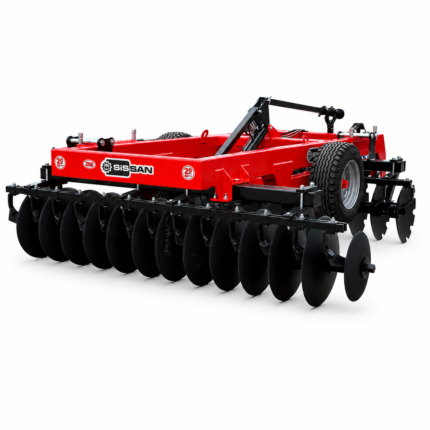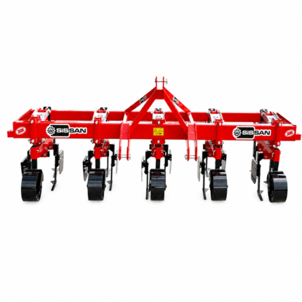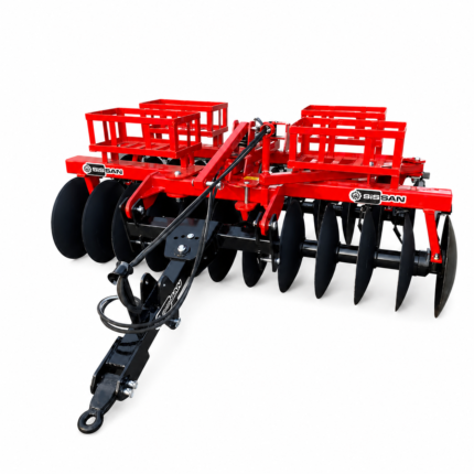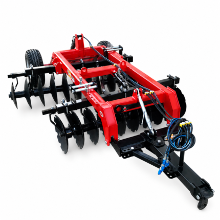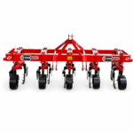


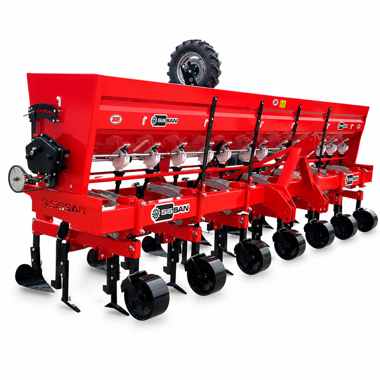
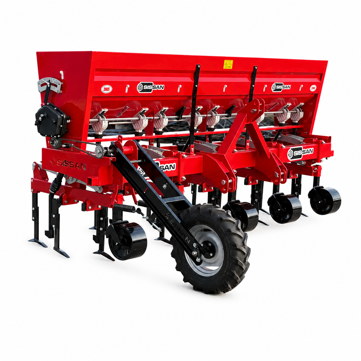
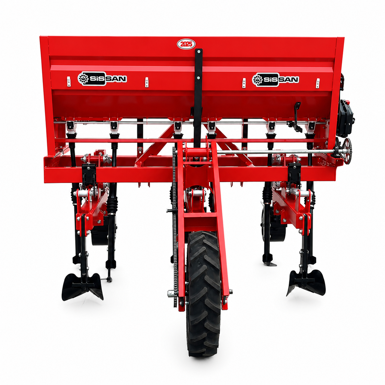
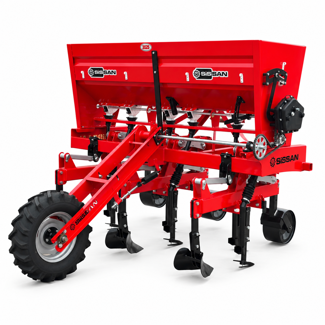
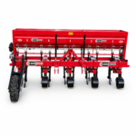
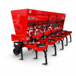
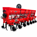
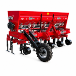
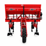
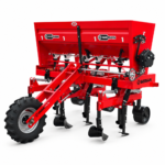
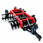

Inter-Row Cultivator with Independent Row Units and Fertilizer Applicator
The SİSSAN Inter-Row Cultivator with Independent Row Units and Fertilizer Applicator
performs cultivation and fertilizer application in a single pass. Its independently
suspended row units follow the ground, control weeds and place fertilizer precisely
alongside the crop rows.
Spring-Tine • PTO-Driven
Front-Wheel • Rear-Wheel
Cultivation and Fertilization
in One Pass, Precisely Along Every Row.
The SİSSAN Inter-Row Cultivator with Independent Row Units and Fertilizer Applicator is designed to control weeds mechanically, loosen the soil, break surface crust and place crop nutrients precisely alongside row crops.
Its independently suspended cultivating units adapt to variations in the field surface. Performing cultivation and fertilizer application in the same pass helps reduce field traffic, operating time and the need for separate applications.
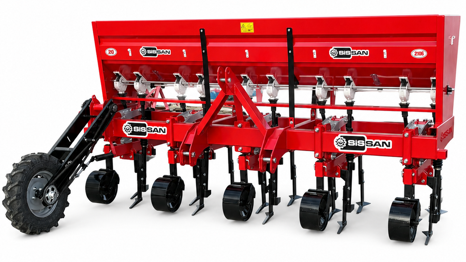
Feed the Crop While Cultivating the Soil
In conventional practice, inter-row cultivation and side-dressing may be performed as two separate operations at different times. The SİSSAN Inter-Row Cultivator with Independent Row Units and Fertilizer Applicator combines both operations in one working pass, providing more organised and practical crop care.
The cultivating tines loosen the soil while cutting weeds at the root zone between crop rows. At the same time, granular fertilizer metered from the hopper is directed to the required row zones through the distributor outlets and telescopic hoses.
Instead of being broadcast randomly over the field surface, the fertilizer is delivered to positions suited to the working pattern. The application rate can be adjusted on the machine according to fertilizer type, crop growth stage, row spacing and the fertilization programme.
Strong, stable operation that follows the soil surface along every row.
Strong, Adjustable Construction for Demanding Field Conditions
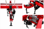
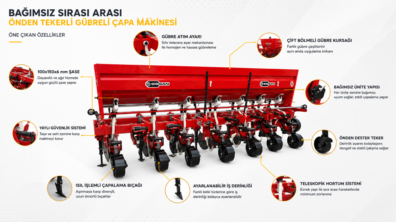
Independent Cultivating Units
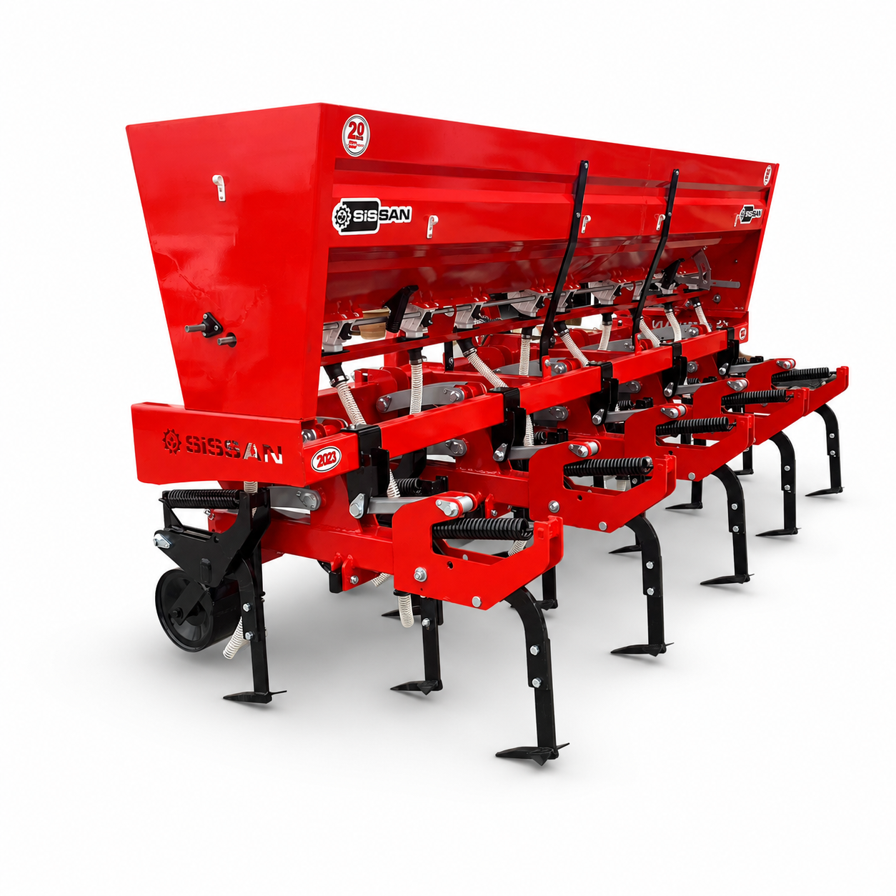
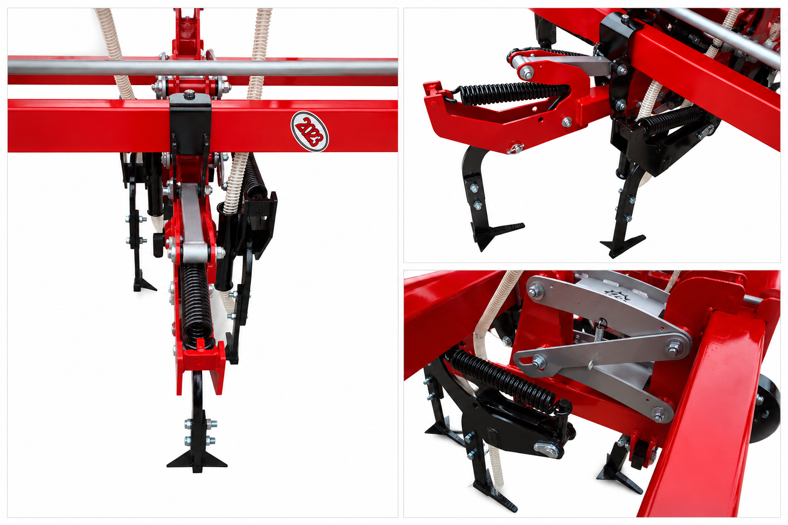
Each cultivating unit follows the field surface independently. On undulating and variable ground, this design prevents all units from being forced to remain at the same height and supports more even cultivation.
Heavy-Duty 100×150×6 mm Main Frame
The reinforced main frame is designed to carry the fertilizer hopper, independent row units, linkage arms and loads generated by the working tools in a balanced manner.
Precision Fertilizer-Rate Adjustment
The adjustment mechanism on the fertilizer-metering system allows the output rate to be controlled. Correct calibration supports even application across all rows.
Dual-Outlet Fertilizer Distributor
The dual-outlet distributor directs fertilizer to the required working zones. Depending on the application setup, it can place fertilizer on both sides of the crop row.
Independent Depth-Control Wheels
Gauge wheels operating with each unit help prevent the cultivating tools from penetrating too deeply or running too shallow. They make it easier to maintain the selected working depth.
Telescopic Fertilizer Hoses
The flexible telescopic hose system allows the fertilizer delivery lines to follow the vertical movement of the independent row units.
Spring-Loaded Protection System
If a tine encounters a stone, hard clod or similar obstruction, the spring-loaded design absorbs the impact and helps protect the cultivating tool and linkage components.
Heat-Treated Cultivating Blades
The soil-engaging blades are manufactured from heat-treated material to provide wear resistance, long service life and dependable cutting performance.
Each Unit Follows the Field Surface Independently
On conventional rigid-frame cultivators, sudden rises or depressions in the field surface can affect the entire working width. In the independent system, each row unit moves through its own linkage mechanism and gauge wheel.
The rise or fall of one unit does not directly alter the operating position of the neighbouring unit. This provides more controlled operation on uneven fields, land marked by irrigation tracks or ground with variable surface conditions.
The unit’s freedom of movement helps the blades work close to the selected depth, improves consistency between rows and gives the operator greater control when working near the crop.
Places Nutrients Beside the Crop During Its Growth Stage
Granular fertilizer loaded into the upper hopper is fed into the ground-driven metering mechanism. The selected amount is transferred from the distributors into telescopic hoses and delivered to the working rows.
The output rate depends not only on the position of the adjustment lever, but also on granule size, flow characteristics, moisture content, tractor forward speed and the circumference of the drive wheel. A fixed-distance calibration test should therefore be performed before field operation whenever the fertilizer type changes.
During calibration, confirm that every fertilizer outlet is open, the hoses are not kinked and the distributors contain no foreign material. Comparing the quantity delivered from each outlet is important for uniform application between rows.
Row Configurations for Different Field Sizes and Planting Patterns
3-Row Model
A compact solution for small and medium-sized fields, narrow field entrances and operations requiring high manoeuvrability.
Its narrower overall working width facilitates headland turns and supports balanced operation with a suitably powered tractor.
5-Row Model
A balanced choice in terms of work capacity, machine width and tractor compatibility. It is suitable for medium and large production areas.
It is designed to increase daily output while retaining a manageable working width for headland turns.
7-Row Model
Works more inter-row spaces in a single pass to deliver high daily capacity on large fields.
Selection should take account of tractor lift capacity, front-ballast balance, road width, field entrances and the planter’s row pattern.
Spring-Tine or PTO-Driven Solutions for Different Soil Conditions
Spring-Tine Cultivator Option
On the spring-tine model, soil cultivation is performed by tines and shares working through the tractor’s forward movement. The blades cut weeds at the root zone while loosening the soil between rows.
In stony fields or soils containing hard and variable areas, the spring tines deflect when they encounter an obstruction and help reduce direct impact loads on the frame.
This option is suitable for operations seeking a simple drive arrangement, easy adjustment and low maintenance requirements.
PTO-Driven Rotary Cultivator Option
The PTO-driven model receives power from the tractor PTO. Its rotating working elements actively break the soil between rows and produce more intensive crumbling.
It can be considered where surface crusting is severe, greater soil breakdown is required or weed pressure is high.
PTO speed, tractor forward speed and working depth must be adjusted in relation to one another. Never operate the machine without the PTO shaft guard in place.
Front-Wheel or Rear-Wheel Configuration
Front-Wheel Model
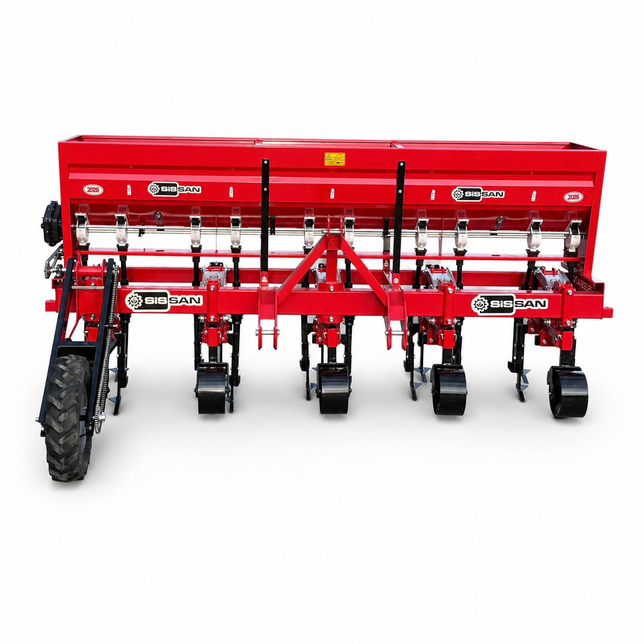
In this configuration, the main drive wheel is positioned at the front of the machine. It transfers motion to the fertilizer-metering system and supports machine stability during operation.
The front-wheel layout may be selected according to tractor-linkage geometry, crop height, row spacing and field-surface conditions.
Rear-Wheel Model
In this configuration, the main drive wheel is positioned behind the cultivating units. It offers an alternative machine layout for different field conditions and operator preferences.
When choosing a front- or rear-wheel system, consider crop growth stage, leaf spread, headland turns and the drive wheel’s ability to maintain continuous soil contact.
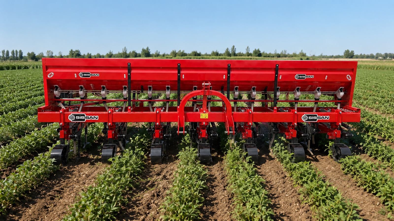
Four Essential Adjustments Before Entering the Field
Set the Row Spacing
Position the units on the main frame according to the actual row centres created by the planter. Use the measured spacing in the field rather than relying only on catalogue dimensions.
Set the Working Depth
Adjust the gauge wheels and cultivating tools deeply enough to control weed roots without damaging the crop’s root zone.
Calibrate the Fertilizer System
Over a measured distance, collect and weigh the fertilizer discharged from each outlet separately. Adjust the metering mechanism until the target rate is reached.
Perform a Low-Speed Test Pass
Before normal operation, make a short test pass. Check crop safety, blade position, row tracking, fertilizer flow and working depth.
Effective Crop Care for Many Row-Planted Crops
The machine can be used for the care of different row crops, provided that row spacing and working units are adjusted correctly.
Maize and Sunflower
Suitable for cutting weeds between rows, breaking surface crust and side-dressing during the crop’s growth stage.
Peanuts and Soybean
With suitable adjustment to the crop rows, it can be used for weed control and shallow soil cultivation. The crop-development stage is particularly important when working in peanuts.
Cotton and Sugar Beet
Precise row tracking helps protect young plants, clean the inter-row area and loosen the soil.
Potatoes, Tobacco and Vegetables
In field and vegetable production with suitable row widths, the cultivating tools, depth and fertilizer-delivery points can be adjusted to the crop.
Do Not Select the Machine by Row Count Alone
The most suitable model should be selected by considering tractor hydraulic lift capacity, front-to-rear weight balance, planter row count, actual row spacing, soil conditions and field size as well as tractor power.
- Small and fragmented fields:
Consider highly manoeuvrable 3-row models. - Medium-sized operations:
A 5-row model can provide a good balance between capacity and ease of use. - Large, regularly shaped fields:
A 7-row model can provide high daily output with fewer passes. - Stony and variable soils:
Spring-tine tools that deflect under impact can offer an advantage. - Conditions requiring intensive crumbling:
The PTO-driven rotary system can be selected. - Drive-wheel position:
Consider field layout, crop development, machine balance and continuous ground contact of the drive wheel.
Correct Adjustment, Correct Timing and Controlled Forward Speed
Successful inter-row cultivation depends on more than machine design. Operating when weeds are still small and soil moisture is suitable directly affects work quality.
Excessively wet soil may stick to the blades and adversely affect the distributors and wheels. In very dry, hard ground, blade penetration may become difficult and loads on the working components may increase.
Set tractor speed according to crop size, the safe working clearance between rows, weed pressure and soil conditions. Reduce speed when approaching the crop and follow the row centre consistently.
A Brief Check Before Every Use Supports Safe Operation Throughout the Season
- Inspect the three-point-linkage connections and safety pins.
- Do not operate with loose frame joints, row-unit connections or blade bolts.
- Check cultivating blades for bending, breakage and excessive wear.
- Confirm that the gauge wheels rotate freely and are set to the same depth.
- Clean fertilizer distributors, metering rollers and outlets after each use.
- Check telescopic hoses for kinks, cracks and blockages.
- Do not leave fertilizer in the hopper at the end of the season.
- On PTO-driven models, inspect the PTO shaft, universal joints and protective guards.
- Lubricate all grease points at the intervals specified in the operator’s manual.
Three Row Configurations.
Four Working-System Combinations.
With 3-, 5- and 7-row versions and spring-tine, PTO-driven, front-wheel and rear-wheel options, the SİSSAN Inter-Row Cultivator with Independent Row Units and Fertilizer Applicator can be configured to suit your planting pattern and field conditions.
Take control of inter-row crop care with SİSSAN.
| Number of Units | 3-Row, 5-Row, 7-Row |
|---|---|
| Select a Model | Front-Wheel Model, PTO-Driven Model, Rear-Wheel Model, Spring-Tine Model |
Inter-Row Cultivator with Independent Row Units
and Fertilizer Applicator
A professional crop-care solution available in 3-, 5- and 7-row configurations,
designed to adapt to different planting patterns and perform inter-row cultivation
and fertilizer application in a single pass.
Spring-Tine • PTO-Driven
Front-Wheel • Rear-Wheel
Independent Row Units
| Technical Feature | Standard / Option | Description |
|---|---|---|
| Machine Type | Mounted inter-row cultivator with fertilizer applicator | Attaches to the tractor's three-point linkage. |
| Row Configurations | 3-row, 5-row and 7-row | Selected according to field size, planting pattern and tractor capacity. |
| Working System | Spring-tine or PTO-driven | Choice of passive cultivating tines or an active rotary system driven by the tractor PTO. |
| Drive-Wheel Position | Front-wheel or rear-wheel | The fertilizer-metering drive wheel is positioned according to the selected model. |
| Main Frame | 100×150×6 mm | Reinforced main frame supporting the fertilizer hopper and independent row units. |
| Row-Unit Design | Independently suspended | Each row unit follows rises and depressions in the field independently. |
| Row-Unit Mounting | Articulated suspension system | Helps the units follow the soil surface and maintain stable operation. |
| Working Depth | Adjustable | Set according to crop development, soil conditions and weed pressure. |
| Depth Control | Independent gauge wheels | Helps each row unit maintain the selected working depth. |
| Cultivating Blades | Heat-treated | Designed for wear resistance, long service life and reliable cutting performance. |
| Protection System | Spring-loaded protection | Helps protect working components against stones, hard clods and sudden impacts. |
| Fertilizer Hopper | Varies by machine width | Hopper capacity is determined by the number of rows and the ordered configuration. |
| Fertilizer Type | Granular mineral fertilizer | Designed for applying free-flowing granular fertilizer alongside crop rows. |
| Application-Rate Adjustment | Precision mechanical adjustment | Allows the application rate to be set according to the crop and fertilization programme. |
| Fertilizer Distributor | Dual-outlet | Helps direct fertilizer evenly to separate delivery outlets. |
| Fertilizer Hoses | Telescopic and flexible | Maintains a compatible fertilizer flow path while the independent units move vertically. |
| Fertilizer Metering Drive | Ground-driven | Forward movement of the machine drives the fertilizer-metering mechanism. |
| Row Spacing | Adjustable | Row units are positioned according to the actual row centres created by the planter. |
| Overall Working Width | Depends on row spacing and row count | Varies according to the planting pattern on 3-, 5- and 7-row models. |
| Paint System | Shot blasting, epoxy primer and acrylic topcoat | Provides long-lasting surface protection against outdoor and field conditions. |
| Suitable Crops | Row crops | Maize, sunflower, cotton, peanuts, soybean and similar crops. |
| Technical Data | 3-Row Model | 5-Row Model | 7-Row Model |
|---|---|---|---|
| Number of Independent Row Units | 3 | 5 | 7 |
| Working System | Spring-tine / PTO-driven | Spring-tine / PTO-driven | Spring-tine / PTO-driven |
| Wheel Configuration | Front / rear | Front / rear | Front / rear |
| Row Spacing | Adjusted to the planting pattern | Adjusted to the planting pattern | Adjusted to the planting pattern |
| Overall Working Width | Depends on unit spacing | Depends on unit spacing | Depends on unit spacing |
| Recommended Tractor Power | 45–60 HP | 60–80 HP | 80–100 HP |
| Tractor Connection | Three-point linkage | Three-point linkage | Three-point linkage |
| Recommended Use | Small and fragmented fields | Medium and large fields | Large, regularly shaped fields |
| Manoeuvrability | High | Balanced | Requires sufficient headland space |
| Daily Work Capacity | Compact operation | Medium to high capacity | High capacity |
ranges for the spring-tine model. The PTO-driven system, a full fertilizer hopper,
heavy soil, sloping terrain and wider row spacing may require greater tractor power
and hydraulic lift capacity.
| Feature | Spring-Tine Model | PTO-Driven Model |
|---|---|---|
| Operating Principle | Cultivating tines work through the tractor's forward movement | Rotary blades are driven by the tractor PTO |
| PTO Required | No | Yes |
| Recommended PTO Speed | Not applicable | 540 rpm |
| Tillage Intensity | Shallow cutting and soil loosening | Active soil breaking and more intensive crumbling |
| Weed Control | Cuts and uproots weeds at the root zone | Shreds and uproots weeds with rotary blades |
| Suitable Field Conditions | General use and variable soils | Crusted soils and conditions requiring intensive crumbling |
| Maintenance Requirement | Lower | Higher due to the PTO shaft, gearbox and moving components |
| Tractor Power Requirement | Lower | Higher depending on configuration |
| Feature | Front-Wheel Model | Rear-Wheel Model |
|---|---|---|
| Drive-Wheel Position | In front of the cultivating units | Behind the cultivating units |
| Primary Function | Drives the fertilizer system and provides front support | Drives the fertilizer system and follows from the rear |
| Selection Criteria | Tractor linkage, crop structure and operator preference | Field layout, headland space and machine configuration |
| Row-Unit Gauge Wheels | Fitted independently | Fitted independently |
| Inspection Step | Procedure |
|---|---|
| 1. Check the Fertilizer | Use dry, free-flowing, lump-free granular fertilizer. |
| 2. Check the Outlets | Confirm that all distributors and hoses are open and unobstructed. |
| 3. Set the Test Distance | Operate the machine over the specified distance under normal working conditions. |
| 4. Collect the Fertilizer | Collect and weigh the fertilizer from each outlet separately. |
| 5. Correct the Setting | Adjust the metering mechanism until the target application rate is reached. |
| 6. Check Uniformity | Compare the fertilizer quantities delivered to each row. |
Fertilizer rate (kg/ha) = Collected fertilizer (kg) × 10,000 ÷
[Test distance (m) × effective working width (m)]
capacity, overall width and transport dimensions vary according to the number
of row units, spring-tine or PTO-driven system, wheel position and ordered
equipment. Tractor selection must take account not only of engine power, but
also hydraulic lift capacity, front-ballast balance and the load of a full hopper.